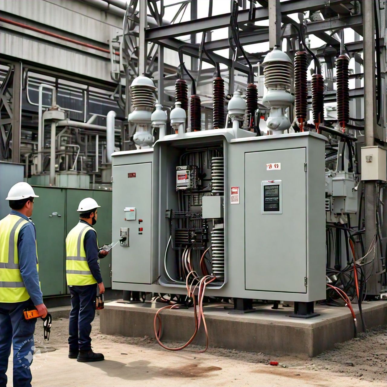
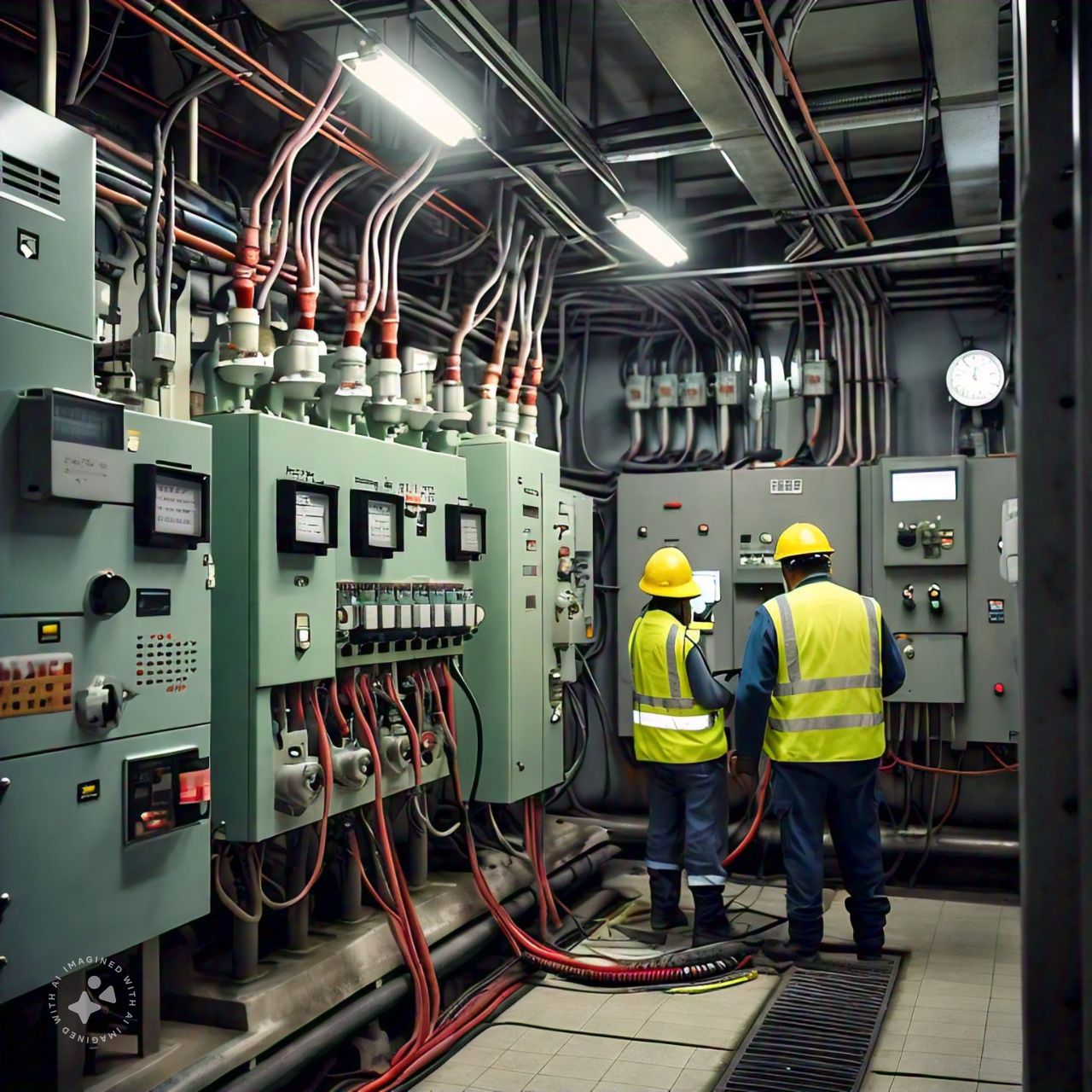
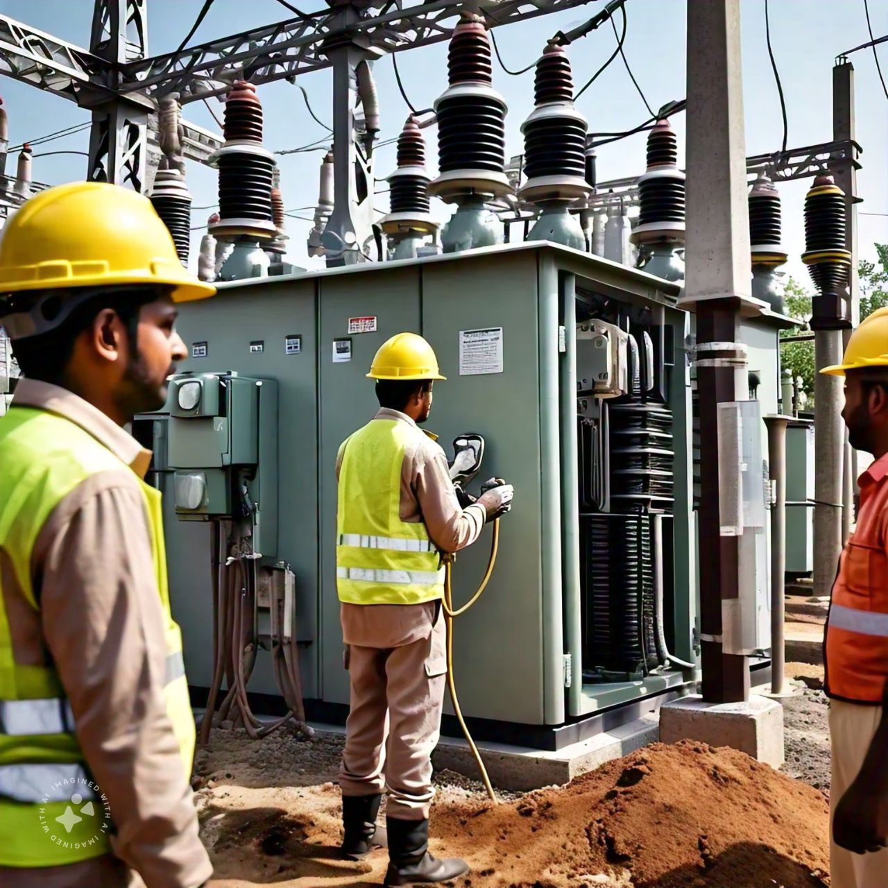
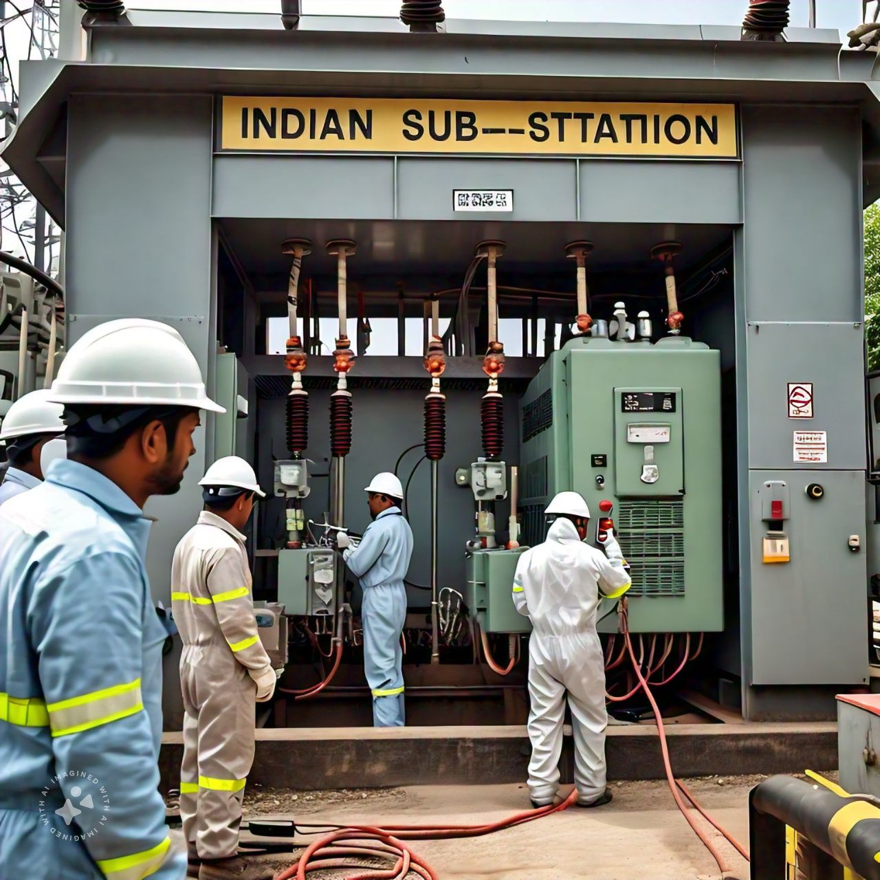
Relay Testing, Primary & Secondary Current Injection, Earth Resistance Testing, and High Voltage Testing of Sub-Stations up to 33 kV
Ensuring the reliability and safety of sub-stations up to 33 kV involves rigorous testing and maintenance procedures. Key among these are relay testing, primary and secondary current injection, earth resistance testing, and high voltage (H.V.) testing. These tests validate the functionality, protection, and integrity of the electrical components and systems. This guide provides detailed processes and best practices for conducting these essential tests in sub-stations.
Relay Testing
Relays are critical components in sub-station protection schemes, providing automatic fault detection and isolation. Regular testing of relays ensures they function correctly and respond appropriately during fault conditions.
Visual Inspection:
-
- Check for physical damage, corrosion, or signs of wear on the relays.
- Verify proper installation and secure mounting of the relay units.
Functional Testing:
-
- Use relay test sets to simulate fault conditions and verify the relay’s response.
- Test various relay settings, including overcurrent, differential, distance, and earth fault protection.
Calibration:
-
- Ensure the relay settings match the design and operational parameters.
- Adjust the relay settings if necessary, based on the test results.
Trip Testing:
-
- Verify that the relay correctly trips the associated circuit breaker under fault conditions.
- Check the coordination between primary and backup relays to ensure proper fault isolation.
Primary and Secondary Current Injection
Current injection testing is vital for validating the accuracy and functionality of protection relays and current transformers (CTs). There are two types of current injection tests: primary and secondary.
Primary Current Injection:
-
- Setup: Connect a high current source to the primary side of the CTs.
- Testing: Inject a known current through the primary winding and measure the output on the secondary winding to verify the CT ratio and performance.
- Verification: Compare the measured values with the expected values to ensure accuracy and proper functioning.
Secondary Current Injection:
-
- Setup: Connect a current source to the secondary side of the relay circuit.
- Testing: Inject a known current directly into the relay inputs to simulate fault conditions.
- Relay Response: Verify the relay’s response to the injected currents, including timing and accuracy of tripping.
- Adjustment: Calibrate the relay settings if discrepancies are found during testing.
Earth Resistance Testing
Earth resistance testing ensures the effectiveness of the grounding system, which is crucial for safety and fault clearance in sub-stations.
Inspection:
-
- Visually inspect the grounding system for corrosion, loose connections, and physical damage.
- Verify that all grounding components are properly installed.
Testing Methods:
-
- Fall-of-Potential Method: Measure the resistance between the earth electrode and the ground using a series of test probes.
- Clamp-On Method: Use a clamp-on ground resistance tester to measure the resistance without disconnecting the grounding system.
Measurement and Analysis:
-
- Record the resistance values and compare them with the acceptable limits specified by standards.
- Identify and rectify any high resistance points in the grounding system.
Documentation:
-
- Document the test results and any corrective actions taken.
- Maintain records for future reference and compliance purposes.
High Voltage Testing
High voltage (H.V.) testing is conducted to verify the insulation integrity of electrical components and systems, ensuring they can withstand operational and fault conditions.
Preparation:
-
- Isolate the equipment under test and ensure it is free from moisture and contaminants.
- Use appropriate personal protective equipment (PPE) and follow safety protocols.
Testing Methods:
-
- Dielectric Withstand Test: Apply a high voltage to the equipment and measure the leakage current to verify insulation strength.
- Partial Discharge Test: Detect and measure partial discharge activity within the insulation to identify potential weak spots.
Test Execution:
-
- Gradually increase the test voltage to the specified level and hold it for the required duration.
- Monitor the equipment for signs of insulation failure, such as excessive leakage current or visible arcing.
Analysis and Reporting:
-
- Analyze the test results to determine the insulation condition.
- Document the test procedure, results, and any anomalies or failures observed.


